
Numerous polymers are expelled through blown film kicks the bucket to deliver monolayer and multilayer films. The most famous style of pass on being used today to create blown movies is the winding mandrel pass on. This sort of kick the bucket can be utilized successfully for some polymers yet can’t without much of a stretch be utilized with thermally delicate materials because of long stream ways and expansive surface territories that can prompt polymer corruption. This paper will examine another, one of a kind blown film kick the bucket innovation in which a thermally touchy polymer is typified with a less delicate material and handled into a blown film. Exploratory information will be appeared on the thickness of embodied melts and the one of a kind stream designs in the kick the bucket.
Coextrusion is a typical strategy utilized for creating multilayer blown films. Coextrusion is a procedure in which at least two polymers are expelled and combined in a feedblock or kick the bucket to frame a solitary structure with different layers. This procedure enables the processor to consolidate the alluring properties of numerous polymers into one structure with upgraded execution attributes. The coextrusion procedure has been broadly used to deliver multilayer sheet, blown film, cast film, tubing, wire covering, and profiles.
This paper will talk about another, exceptional blown film bite the dust innovation in which a thermally delicate polymer is exemplified with a less touchy material and handled into a blown film. Exploratory information will be appeared on the thickness of typified dissolves and the interesting stream designs in the pass on.
Polymer background
Two styles of coextrusion are outlined in Figure 1.
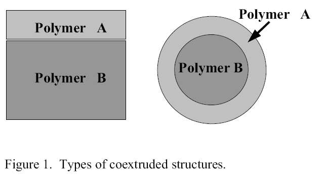
Figure 1. Types of coextruded structures
This figure demonstrates a planar layered structure on the left and an exemplified structure on the right. The exemplified structure can be created utilizing a feedback like the one that is indicated schematically in Figure 2.
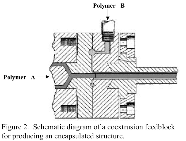
Figure 2. Schematic diagram of a coextrusion feedblock for producing a polymer encapsulated structure
This graph demonstrates a feedblock joined to the finish of an extruder pumping polymer A from the left into an exchange pipe. The pipe encourages the feedblock that radially embodies polymer A with a layer of polymer B. This embodied structure at that point streams downstream keeping up the layered structure.
Figure 3 demonstrates why epitome innovation can be critical for thermally delicate materials.
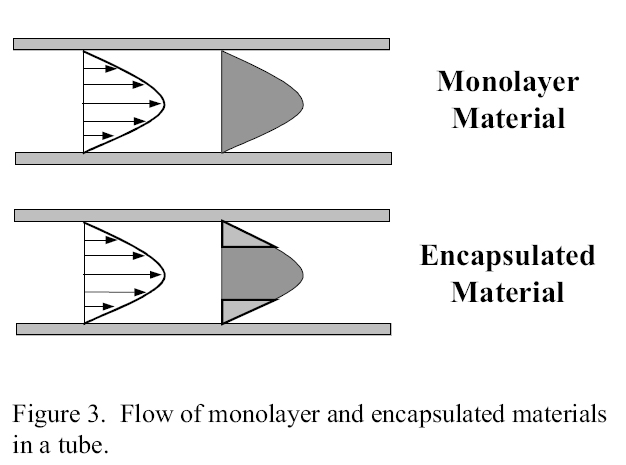
Figure 3. Flow of polymer monolayer and exncapsulated materials in a tube.
This figure demonstrates a portrayal of the speed profile in a tube for a monolayer and an embodied material. The left half of the figure speaks to the speed vectors in the allegorical stream in a tube. The correct side of the figure indicates how in an embodied structure, the center material is restricted to the higher speed zones of the stream and will have a shorter normal living arrangement time. Since debasement of thermally touchy materials is regularly a component of time and temperature, a shorter normal home time would deliver less corruption.
As was portrayed before, most business blown film lines utilize a style of kick the bucket called a winding mandrel. In this kind of pass on, the soften stream is part into a few streams and spiraled around a focal mandrel with the end goal to create a film that is uniform in thickness. This basically delivers thin covering layers of the polymer at the exit. This style of the pass on isn’t appropriate for a typified structure on the grounds that the liquefy stream division and layering would upset the epitome structure.
Since a winding mandrel kick the bucket isn’t appropriate for an exemplified structure, a crosshead style bite the dust was utilized in this examination. In a crosshead style kick the bucket, a dispersion complex like that utilized in a coathanger sheet pass on is folded over around with the end goal that the finishes contact shaping a tubular exit. At the point when an embodied structure, like what is portrayed in Figure 1, is bolstered to a standard crosshead bite the dust, the stream geometry transforms it encounters are appeared in Figure 4.
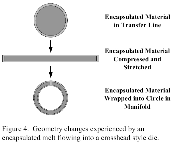
Figure 4. Geometry changes experienced by a polymer excapsulated melt flowing into a crosshead style die
The epitomized structure appeared in the highest point of the figure is packed one way and extended the other way and after that folded over the focal mandrel with the end goal that the closures meet, as is appeared in the base of the figure.
The trouble with this structure is that when the closures of the epitomized structure return together at the of the complex, the skin layers consolidate however the center materials don’t contact. On the off chance that the center material is a boundary polymer and the skin material isn’t, this sort of structure would deliver a film in which the hindrance properties at the weld line are altogether more awful than those in whatever is left of the structure.
One interesting arrangement that creates a tubular structure with uniform obstruction properties has appeared in Figure 5.
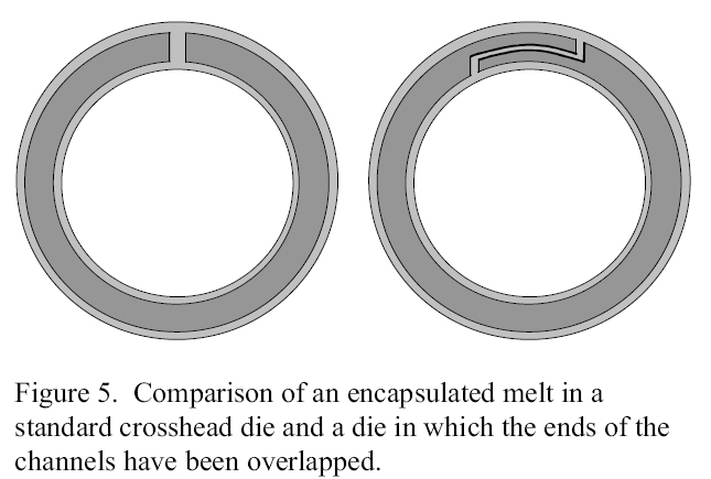
Figure 5. Comparison of a polymer encapsulated melt in a standard crosshead die and a die in which the ends of the channels have been overlapped
The left half of this figure demonstrates a structure delivered by a standard crosshead bite the dust while the correct side of the figure demonstrates a structure created by a one of a kind kick the bucket in which the finishes of the channels have been covered. Figure 6 demonstrates a development of simply the joining territory of the tubular structure in which the boundary layer has been covered.
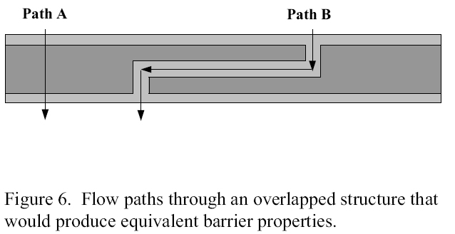
Figure 6. Flow paths through an overlapped structure that would produce equivalent barrier properties for polymer articles
Way A speaks to the stream way of a gas pervading straight through the skin material and the hindrance center layer. Way B speaks to the stream way of a gas penetrating right through the non-obstruction skin material in the cover territory. By knowing the relative boundary properties of the skin and center materials, the cover structure can be outlined with the end goal that Path An and Path B deliver proportionate obstruction properties. This style of the pass on would deliver a tubular film with equivalent hindrance properties around the film.
One of the troubles in outlining a tubular bite the dust for conveying a typified soften is deciding the rheology of the exemplified structure. The reason for this work was to tentatively gauge the rheology of an epitomized structure and to utilize that data to plan a tubular kick the bucket for delivering a film with uniform obstruction properties with a thermally delicate center material.