
A few economically accessible pitches were utilized in these examinations: a high effect polystyrene sap (HIPS), a low thickness polyethylene gum (LDPE), a polyvinylidene chloride obstruction tar (PVDC), every one of the three made by The Dow Chemical Company, and an ethylene-vinyl acetic acid derivation copolymer (EVA) fabricated by DuPont. The rheological properties of the polystyrene and polyethylene tars were demonstrated already on the link.
Two sorts of tests were kept running in this examination. The primary arrangement of trials was rushed to decide the thickness of coextruded exemplified structures. The second arrangement of investigations was hurried to decide the stream examples of typified softens through various bite the dust geometries.
The coextrusion line utilized in this examination for deciding the thickness of an epitomized coextruded structure comprised of a 63.5 mm (2.5 inches) breadth, 21:1 L/D single screw extruder and a 31.75 mm (1.25 inch) distance across, 24:1 L/D single screw extruder. These extruders were joined to a feedblock that was intended to deliver coextruded structures comprising of a center layer typified by a skin layer. The layered structure comprised of a 10% skin layer and a 90% center layer. Appended to the exit of the feedblock was a moving line in which weight transducers had been embedded at particular lengths down the pipe as is appeared in Figure 7. The pipe had a measurement of 9.5-mm (0.375 inches) with a separation of 107 mm (4.2 inches) between the transducers.
The rheology test of those two polymer
For the rheology tests, the coextrusion line was kept running with the two extruders pumping at set stream rates and temperatures until the point when enduring state conditions had been come to. At this condition, the weights from the three transducers were recorded alongside the deliberate aggregate stream rate and temperature. This method was rehashed at a few diverse stream rates and temperatures so the consistency of the typified structure could be resolved at various shear rates.
The coextrusion line utilized for looking at the interface area in coextruded structures comprised of a 31.75 mm (1.25 inch) distance across, 24:1 L/D single screw extruder and a 19.05 mm (0.75 inches) breadth, 24:1 L/D single screw extruder. These extruders were joined to a feedblock that was intended to create coextruded structures comprising of a center layer epitomized by a skin layer. The layered structure comprised of a 30% skin layer and a 70% center layer. Coextruded structures were made utilizing a similar material in each extruder with various shaded colors added to each to permit assurance of the interface area in the structure.
Appended to this feedblock were passes on containing channels with a tear molded cross area and a coathanger style kick the bucket complex with a rectangular shape. These direct were depicted already in detail. Both bite the dust channels had rough lengths of 61 cm.
For a run of the mill explore, the coextrusion line was kept running for 30 minutes to guarantee that relentless state conditions had been come to. The examinations were kept running at a temperature of 215 Celsius degree and an expulsion rate of 2.5 kg/h, which would give a divider shear rate in the scope of 1 to 10 s-1. Variable profundity thermocouples were utilized to gauge the temperature of each liquefies stream only preceding their entering the feedblock. This was done to guarantee that the soften temperature of each stream was the equivalent as they entered the feedblock. At the point when the consistent state was achieved, the extruders were halted all the while and the coextruded material was cooled while still in the pass on the channel, hardening the material. After it had cooled to room temperature, the polymer “heel” was expelled from the kick the bucket and cut into 25.4 mm (1 inch) segments to uncover the cross-sectional faces along the bite the dust. These appearances were examined by acquiring advanced pictures with a camcorder and a proper amplification focal point. This technique permitted the real distortions of the interfaces to be analyzed.
Results kepts running with polymer
The trial setup appeared in Figure 7 was kept running with LDPE gum to approve that the rheological information delivered by this contraption would associate with information produced by standard narrow rheometers.

Figure 7. Polymer Viscosity measurement apparatus for coextruded strcutures
demonstrates the consistency versus shear rate information created for the LDPE pitch utilizing the three unique blends of weight transducers (P1-P2, P2-P3, and P1-P3).
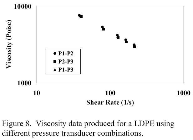
Figure 8. Polymer viscosity data produced for a LDPE using different pressure tranducer combinations
As the figure appears, every one of the three mixes delivered comparable bends. This information additionally connected exceptionally well with information produced by a slender rheometer.
This device was then used to gauge the consistency of an embodied structure comprising of a skin layer of EVA on a center layer of PVDC, and additionally solid structures of the individual parts. This information have appeared in Figure 9.
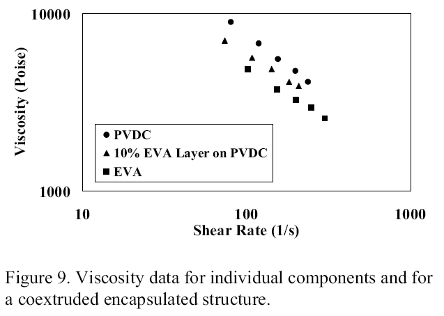
Figure 9. Polymer Viscosity data for individual components and for a coextruded encapsulated structure
At the test conditions utilized, the PVDC center tar had the most elevated thickness, the EVA skin tar had the least consistency, and the exemplified structure had a middle of the road thickness between the center and skin tars.
This thickness information were then used to outline a bite the dust complex with the closures of the channels covered. Extraordinary consideration was taken fit as a fiddle of the circulation complex channels. Past work (11-18) has demonstrated that kick the bucket channel shape is a basic factor in creating coextruded structures with uniform layers, particularly for very viscoelastic materials. This is delineated by the pictures in Figure 10.
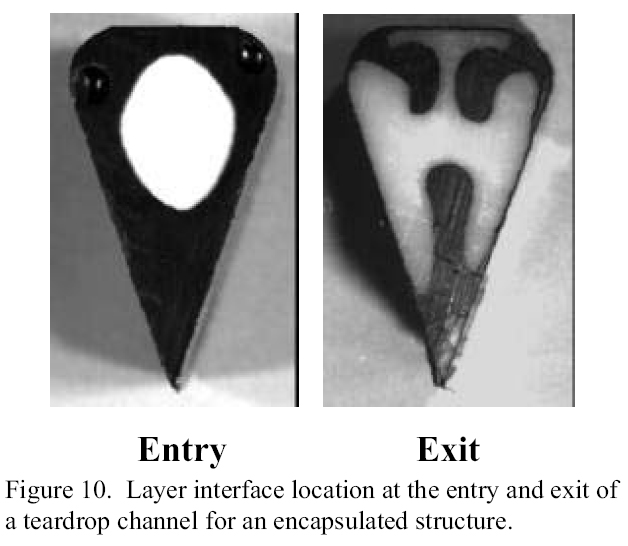
Figure 10. Layer interface location at the entry and exit of a tearsdrop channel for a polymer encapsulated structure
These pictures demonstrate an epitomized structure containing HIPS in the two layers streaming down a tear molded channel. The picture on the left demonstrates the typified structure close to the passage of the channel while the picture on the correct demonstrates the structure close to the exit of the channel. Note the vast misshapening of the white center layer as it streams down the channel. On the off chance that the white material was an obstruction material, this vast measure of twisting would deliver a film structure in which the hindrance properties would not be uniform all through the film.
An embodied soften of HIPS was likewise expelled through an exploratory bite the dust complex with a rectangular cross-sectional shape. The aftereffects of this examination are appeared in Figure 11.
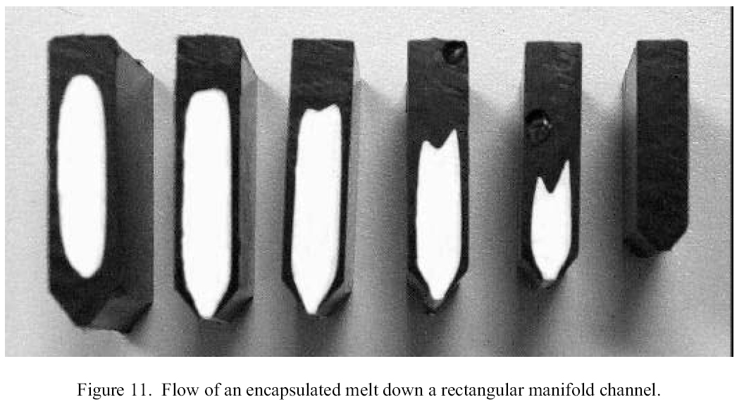
Figure 11. The Flow of a polymer encapsulated melt down a rectangular manifold channel
This figure indicates cross-sectional cuts at interims of 102 mm (4 inches) from close to the passage of the complex on the left to close to the finish of the complex on the right. Note that the dark embodying material turns into a bigger extent of the territory of the complex as it streams down the complex. At a separation of roughly 508 mm (20 inches) down the 610 mm (24 inch) complex, the whole cross segment is made out of dark skin material as it were. This suggests most of the material in the cover region of a crosshead bite the dust would be made out of the skin material utilizing this particular kick the bucket geometry. This outlines the significance of the state of the kick the bucket complex when running an embodied structure.
Utilizing the aftereffects of the majority of the above trials, an expansive scale bite the dust complex was intended for an EVA/PVDC typified structure with a covered weld line. This complex was utilized as the focal layer in a five layer blown film bite the dust to deliver a coextruded film structure in which uniform hindrance properties were created in every aspect of the film.
An extraordinary multilayer coextrusion blown film pass on has been created utilizing epitome innovation to secure the thermally delicate boundary layer material. This bite the dust utilizes a strategy of covering the finishes of the center layer appropriation complex in a crosshead style pass on to guarantee uniform obstruction properties all through the film. The way to scaling this innovation to huge scale kicks the bucket is the utilization of suitable pass on channel geometry to keep up appropriate layer consistency as the typified material courses through the conveyance complex.