
The injection molding process utilizes molds, ordinarily made of steel or aluminum, as the tool customization. The form has numerous parts, however can be part into two parts. Every half is appended inside the infusion shaping machine and the back half is permitted to slide with the goal that the form can be opened and shut along the shape’s separating line. The two principle parts of the form are the shape center and the shape pit. At the point when the shape is shut, the space between the form center and the shape cavity frames the part cavity, that will be loaded with liquid plastic to make the coveted part. Different pit molds are here and there utilized, in which the two shape parts frame a few indistinguishable part cavities.
Injection molding tooling overview
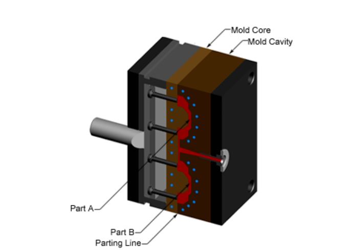
Injection molding tool base
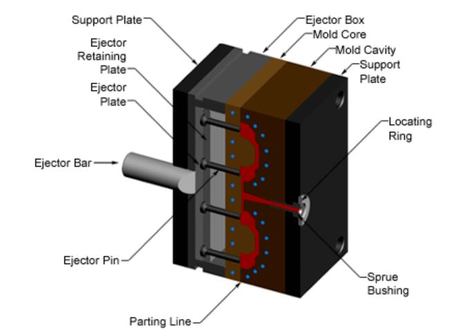
The shape center and form hole are each mounted to the form base, which is then settled to the platens inside the injection molding machine. The front portion of the shape base incorporates a help plate, to which the form pit is appended, the sprue bushing, into which the material will spill out of the spout, and a finding ring, keeping in mind the end goal to adjust the form base with the spout. The back portion of the shape base incorporates the discharge framework, to which the form center is appended, and a help plate. At the point when the bracing unit isolates the shape parts, the ejector bar incites the launch framework. The ejector bar pushes the ejector plate forward inside the ejector box, which thus pushes the ejector pins into the shaped part. The ejector pins drive the set part out of the open form hole.
Injection molding tool base
Injection Moulding Tool Channels
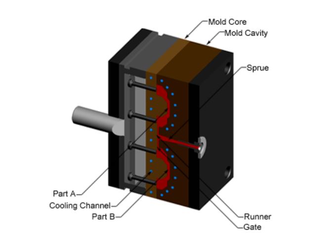
All together for the liquid plastic to stream into the form pits, a few channels are coordinated into the shape plan. In the first place, the liquid plastic enters the form through the sprue. Extra channels, called sprinters, convey the liquid plastic from the sprue to the greater part of the pits that must be filled. Toward the finish of every sprinter, the liquid plastic enters the pit through a door which coordinates the stream. The liquid plastic that cements inside these sprinters is appended to the part and should be isolated after the part has been shot out from the shape. Be that as it may, some of the time hot sprinter frameworks are utilized which freely warm the channels, enabling the contained material to be dissolved and withdrawn from the part. Another kind of channel that is incorporated with the form is cooling channels. These channels enable water to course through the shape dividers, adjoining the pit, and cool the liquid plastic.
Injection molding tool channel
Injection Moulding Tool Design
Notwithstanding sprinters and doors, there are numerous other outline issues that must be considered in the plan of the molds. Right off the bat, the form must enable the liquid plastic to stream effortlessly into the greater part of the depressions. Similarly imperative is the expulsion of the cemented part from the form, so a draft point must be connected to the shape dividers. The plan of the shape should likewise oblige any mind boggling highlights on the part, for example, undermines or strings, which will require extra form pieces. A large portion of these gadgets slide into the part hole through the side of the shape, and are in this manner known as slides, or side-activities. The most well-known kind of side-activity is a side-center which empowers an outer undercut to be shaped. Different gadgets enter through the finish of the shape along the separating course, for example, inside center lifters, which can frame an inner undercut. To shape strings into the section, an unscrewing gadget is required, which can pivot out of the form after the strings have been framed.
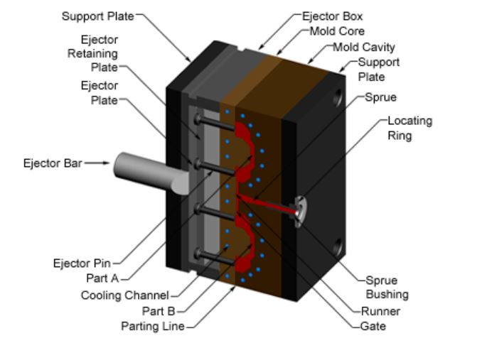
Injection molding tool design – Closed view
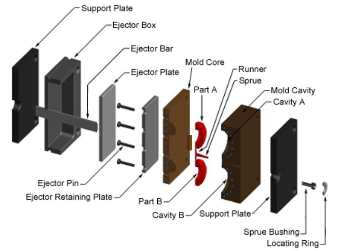
Injection molding tool design – exploded view